
BEST FITLarge VFD and motor-control lineups
Multi-bay floor-standing enclosures
JP Modular & Bayed Cabinets
A modular floor-standing cabinet platform for larger automation, drive and low-voltage control lineups that need multiple joined sections, flexible access and a common mechanical system.
Best suited to projects where the installed equipment, heat, cable-entry zones and maintenance access exceed the practical limits of one standalone enclosure.
Request enclosure quotation Selection is confirmed against dimensions, layout, environment and the approved drawing.
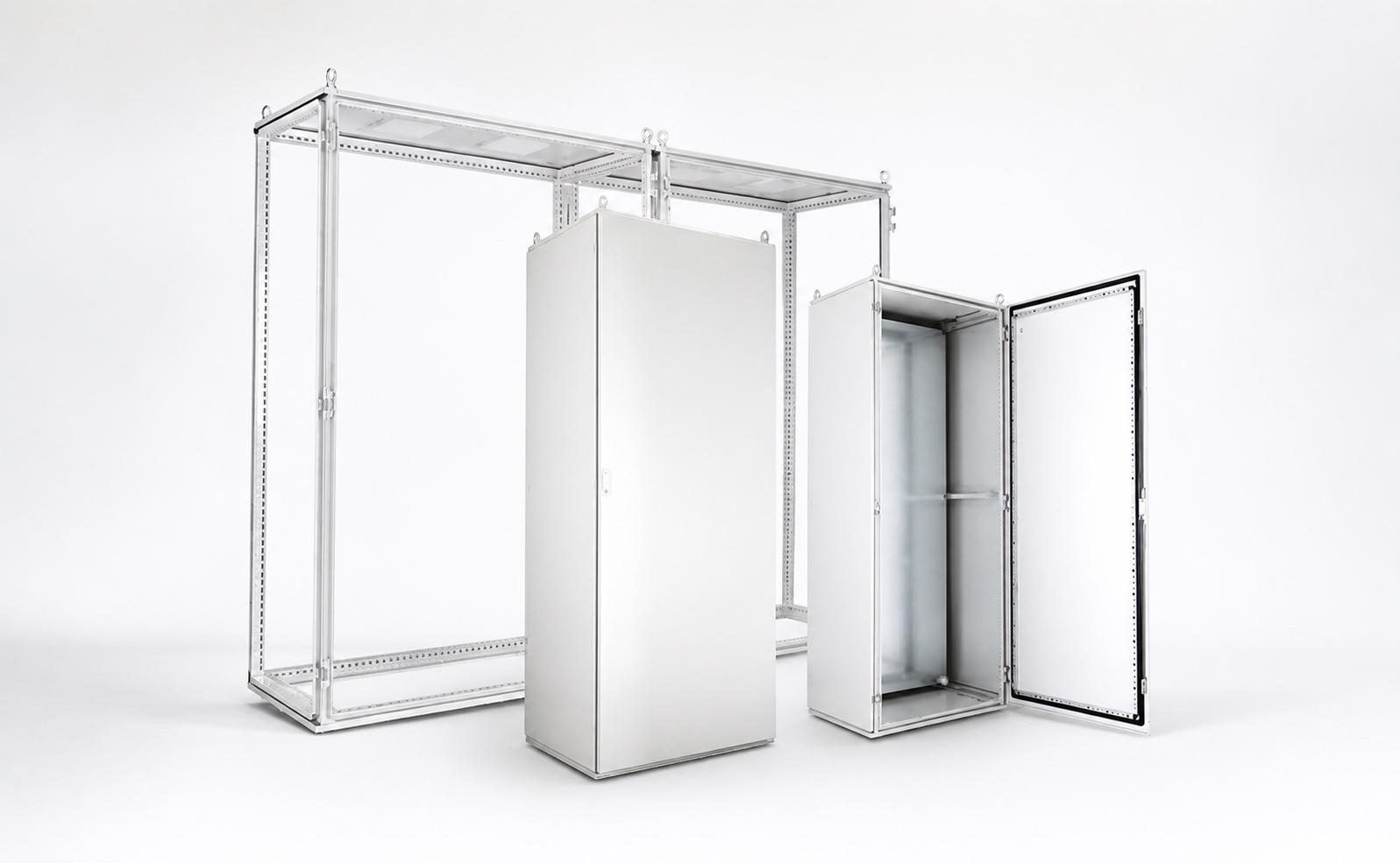 JP product reference · single- and double-door configurations available
KEY PARAMETERConstructionModular frame with removable panels and single- or double-door options
CHECK FIRSTAn enclosure rating does not include unverified field cut-outs or installed accessories
RFQ INPUTEquipment layout and section count
Product views & construction
See the product before selecting the model.
White-background product views show the enclosure format, while the English exploded view identifies the construction. Readable model dimensions are provided as native page content below.
Nine-fold profile frame for standalone or bayed installation, with removable panels and project-defined door arrangement.
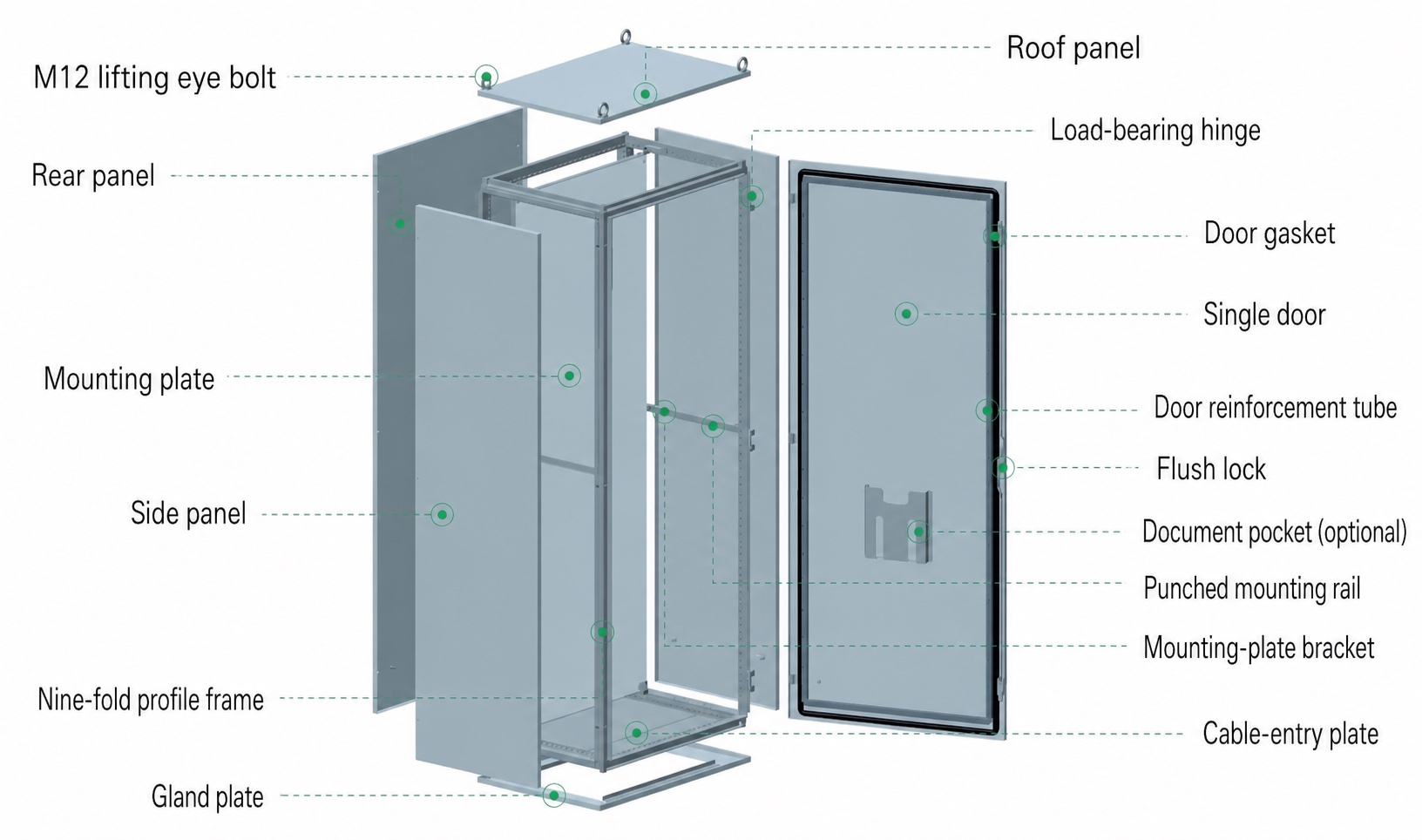
Frame, roof, rear and side panels, mounting plate, gland plate, door reinforcement, gasket and installation beams are shown as separate serviceable parts.
Technical parameters
Selection data
These values describe the enclosure family and the decisions behind selection. The exact construction and dimensions are tied to the confirmed model, option list and approved drawing.
ParameterFamily rangeEngineering note
ConstructionModular frame with removable panels and single- or double-door optionsBaying, partitioning and access sides must be defined from the approved layout.
Reference sheet thickness1.5 mm frame and panels; 2.0 mm doorsFinal thickness and material are confirmed on the enclosure drawing and quotation.
Mounting plate2.5 mm galvanized steel referenceCheck usable area, equipment weight, rail depth and lifting loads.
FinishPowder-coated light gray, RAL 7035 referenceAlternative colors and corrosion protection require project confirmation.
ProtectionIP54 standard design basis; IP55 option by configurationCut-outs, fans, cable entry and field installation can change the achieved rating.
Reference sizes600 or 800 mm W; 1800–2200 mm H; 400–800 mm DTreat these as common planning sizes, not a complete order code.
English dimension reference
Read the drawing codes without zooming into a low-resolution image.
Use these definitions with the model table below. External size is always shown as W × H × D; manufacturing dimensions and cut-outs remain subject to the approved project drawing.
Download original JP source drawing (Chinese)The original factory source is preserved for traceability and may contain Chinese labels. It is not the primary selection information on this page.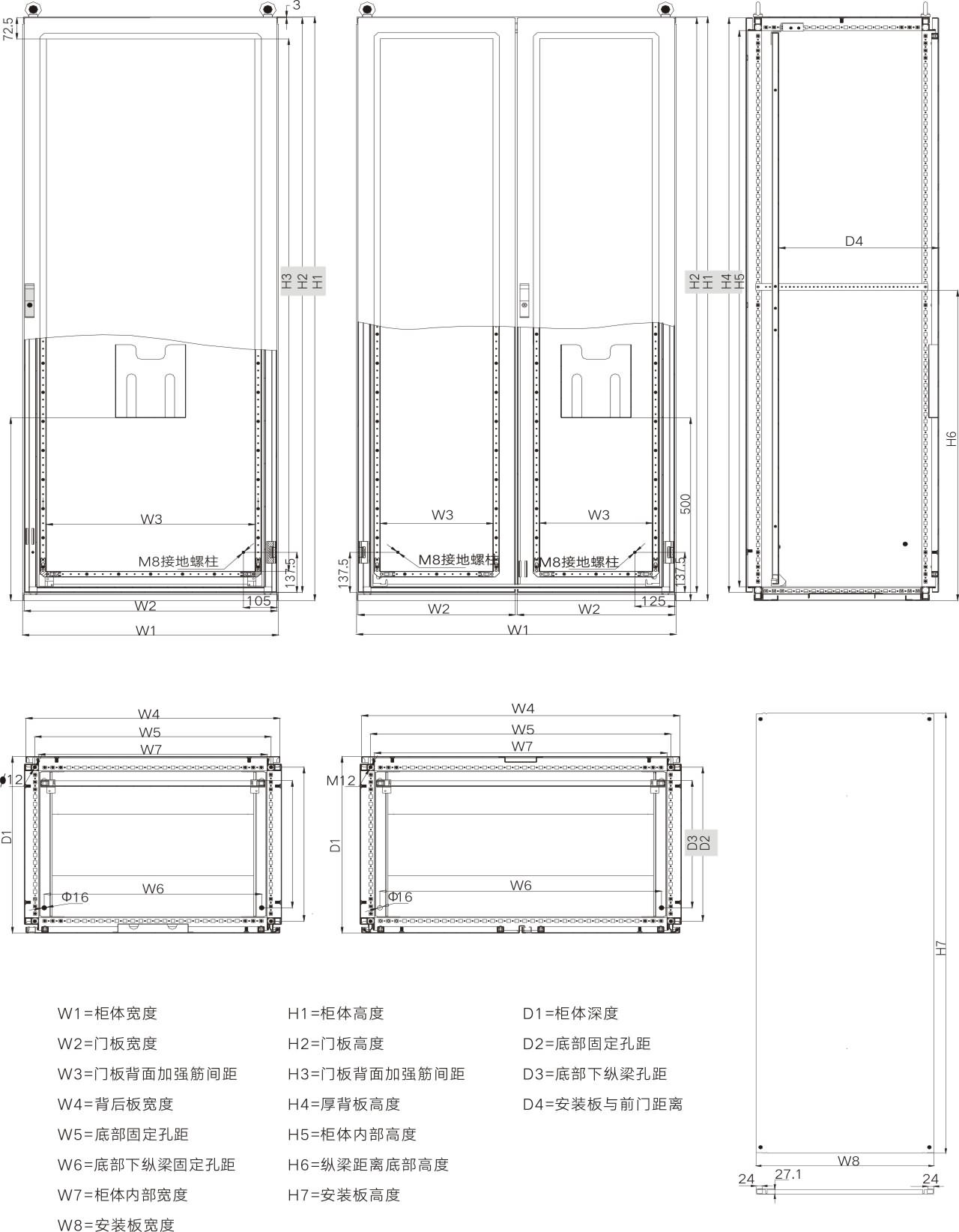
Standard selection matrix
Reference models and usable mounting area.
External size is W × H × D. This table supports early selection; verify usable depth, door arrangement, installation hardware and accessories on the quotation drawing.
ModelExternal size (W × H × D)Mounting plate (W × H)Selection note
JP601840600 × 1800 × 400 mm498 × 1696 mmSingle-door reference
JP801860800 × 1800 × 600 mm698 × 1696 mmSingle-door reference
JP602060600 × 2000 × 600 mm498 × 1896 mmConfirm door and options
JP802060800 × 2000 × 600 mm698 × 1896 mmConfirm door and options
JP602080600 × 2000 × 800 mm498 × 1896 mmConfirm door and options
JP802080800 × 2000 × 800 mm698 × 1896 mmConfirm door and options
JP602260600 × 2200 × 600 mm498 × 2096 mmConfirm door and options
JP802260800 × 2200 × 600 mm698 × 2096 mmConfirm door and options
Dimensions shown are model references. Final manufacturing dimensions, cut-outs, accessories and protection basis follow the approved drawing and quotation.
Common search questions
Quick answers for JP Modular & Bayed Cabinets.
Family guidance narrows the request. The confirmed model, option list and approved drawing remain the final technical identity.
What is JP Modular & Bayed Cabinets best suited for?
Best suited to projects where the installed equipment, heat, cable-entry zones and maintenance access exceed the practical limits of one standalone enclosure. Typical applications include multi-drive control systems, large machine lines, motor-control lineups.
Which information is required to select JP Modular & Bayed Cabinets?
Start with equipment layout and section count, required external w × h × d, door, access and partition arrangement, cable-entry direction and conductor bend radius. Final dimensions, construction and accessories are confirmed on the approved model data and drawing.
Can JP Modular & Bayed Cabinets be quoted from dimensions only?
Dimensions alone do not define material, usable mounting area, door arrangement, IP target, cut-outs, mounting plate or accessories. Honghao confirms the complete enclosure configuration, quantity and destination before releasing the offer.
Good fit
Use it when
- Large VFD and motor-control lineups
- PLC and network cabinet suites
- Production-line control systems
- Projects requiring future bay expansion
Selection limits
Check before specifying
- An enclosure rating does not include unverified field cut-outs or installed accessories
- Mechanical size must be released from the real component layout and thermal study
- Final material, IP claim and dimensions follow the approved project documents
Strengths
Why this family
- Expandable multi-section architecture
- Removable panels for assembly and service
- Common mounting and accessory system
- Suitable for segregated power and control zones
Typical BOM
Accessories
- Plinths and baying kits
- Side and partition panels
- Mounting plates and rails
- Cable-entry and gland plates
- Fans, filters and thermal accessories
Application data
What to send
- Equipment layout and section count
- Required external W × H × D
- Door, access and partition arrangement
- Cable-entry direction and conductor bend radius
- Environment, IP target and thermal-management method
Technical basis
Approved project data remains the final reference.
Family parameters are planning references derived from the current enclosure data set. Honghao confirms the order code, dimensions, construction, cut-outs and protection basis on the approved drawing before production.
Typical applications
Where it is used
RFQ checklist
Get a usable quotation
Send the required W × H × D, equipment or layout drawing, environment, IP target, quantity, options, destination country and required delivery date.
Send BOM or application dataExact configuration