
Motor speed and process control
VFD Control Panels
Complete variable-frequency drive panels engineered around the motor, load, supply network, process controls and destination requirements.
A coordinated drive panel is more than a VFD in an enclosure. Protection, EMC, cooling, bypass philosophy, field I/O and commissioning access must work as one system.
Request project review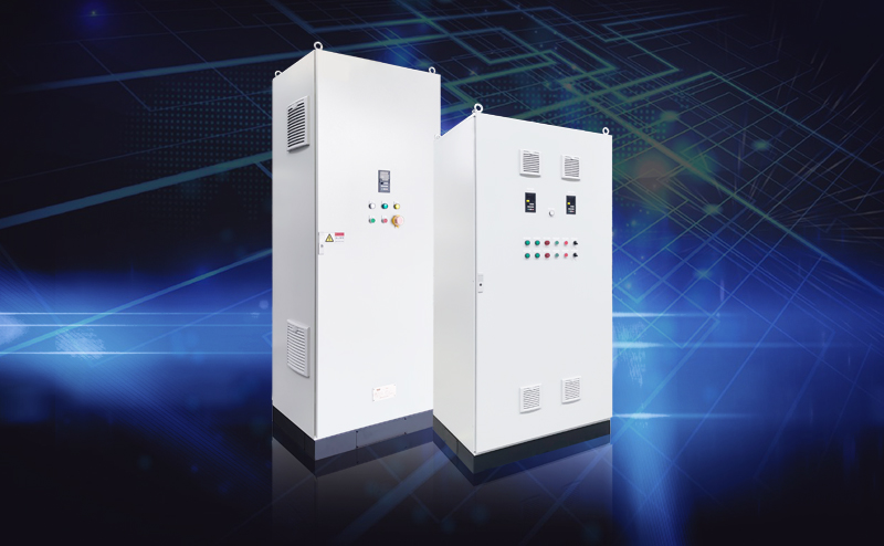
Common VFD Control Panels searches
Questions that change the project scope.
Resolve the first three decisions before the BOM, drawings or FAT plan is released.
01How is a VFD control panel sized?
VFD control panel sizing
Size follows device heat losses, ambient and altitude, enclosure rating, ventilation or cooling, cable space, segregation, service clearances and future allowance. The VFD current and duty remain the starting point; panel dimensions are an outcome.
Open the sizing guide02Does a VFD panel need bypass?
VFD panel bypass design
Bypass is a process-availability choice, not a default. Review whether fixed-speed emergency operation is safe, how the motor is isolated from the drive, interlocking, protection, motor starting current, harmonic behavior and how operators will control the system.
03Which data affects VFD panel cooling?
VFD panel cooling calculation
Drive and accessory losses, switching frequency, load profile, enclosure location, ambient peak, altitude, solar gain, dust, filter maintenance and required IP rating all affect thermal design. Cooling equipment also changes maintenance and power requirements.
Motor speed and process control architecture
How the control system is structured
The blocks below show the normal engineering structure for vfd control panels. The final architecture follows its approved design basis, operating duty and interface boundary.
Incoming power
Main isolator, protective device, surge/line components and metering as specified.
Drive section
SINAMICS V20, G120 or application-matched drive with line/output accessories.
Control
Local/remote selection, start permissives, speed reference, alarms and PLC/fieldbus interface.
Thermal design
Enclosure size, losses, airflow, filters or cooling method based on ambient conditions.
Engineering review
Checks for this design
- Motor full-load current, base frequency and speed range
- Variable- or constant-torque load and overload duty
- Cable length, earthing system and EMC target
- Braking, flying restart, bypass and emergency operation
- Harmonic or power-quality requirements
- Indoor/outdoor ambient, altitude, dust and corrosion
Application data
Inputs for motor speed and process control
- Motor nameplate and quantity
- Load type and operating profile
- Supply voltage/frequency and fault information
- Control philosophy or I/O list
- Enclosure environment and destination
- Required standard, documentation and witness points
Deliverables
Project documents
- Approved BOM and general arrangement
- Single-line and control schematic
- Terminal plan and cable schedule where agreed
- Device parameter record
- Inspection/FAT record
- Packing list and agreed export documents
FAT
Tests for this system
- Visual, labeling and wiring inspection
- Protective conductor continuity
- Control-power and I/O function check
- Drive power-up and parameter verification
- Simulated permissive, alarm and local/remote sequence
- Customer witness or video record when agreed
Related products
Core platforms
Scope boundary
Final compliance scope, short-circuit rating, harmonic performance and field commissioning responsibility must be agreed in writing. A standard FAT does not validate the driven machine or site installation.
Project questions
Before you approve vfd control panels.
Use these answers to define the design basis, FAT evidence and commercial boundary for vfd control panels before production.
VFD Control Panels decisions
Common technical questions before the design basis is approved.
How is a VFD control panel sized?
VFD control panel sizing
Size follows device heat losses, ambient and altitude, enclosure rating, ventilation or cooling, cable space, segregation, service clearances and future allowance. The VFD current and duty remain the starting point; panel dimensions are an outcome.
Open the sizing guideDoes a VFD panel need bypass?
VFD panel bypass design
Bypass is a process-availability choice, not a default. Review whether fixed-speed emergency operation is safe, how the motor is isolated from the drive, interlocking, protection, motor starting current, harmonic behavior and how operators will control the system.
Which data affects VFD panel cooling?
VFD panel cooling calculation
Drive and accessory losses, switching frequency, load profile, enclosure location, ambient peak, altitude, solar gain, dust, filter maintenance and required IP rating all affect thermal design. Cooling equipment also changes maintenance and power requirements.
Scope, testing and quotation
Make deliverables and responsibility clear before production.
What information is required to quote vfd control panels?
VFD Control Panels quotation
Provide motor nameplate and quantity, load type and operating profile, supply voltage/frequency and fault information, control philosophy or i/o list, plus destination, standards basis, required documents and acceptance points. Missing data should be recorded as a quotation assumption.
Send project informationWhat is normally included in the FAT for vfd control panels?
VFD Control Panels FAT
The agreed FAT can cover visual, labeling and wiring inspection, protective conductor continuity, control-power and i/o function check, drive power-up and parameter verification. Tests are limited to the devices and simulations available in the workshop, and do not replace site acceptance.
Review the FAT checklistHow are changes controlled after design approval?
control panel change management
Changes should be logged with the technical reason, affected drawings and BOM, cost or lead-time impact and approval status. Production then follows the latest released revision, and the final package is updated as-built.
See the controlled workflowProject data first